Description
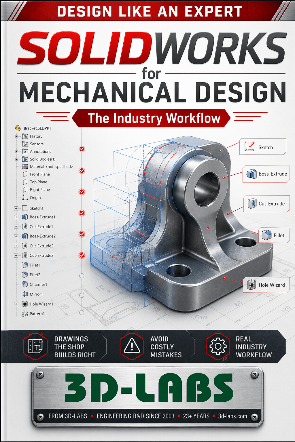
This Solidworks For Mechanical Design eBook from 3D-LABS is written for engineers and students who want a clear, practical reference they can apply immediately.
SolidWorks for Mechanical Design — The Industry Workflow covers SolidWorks parametric modelling from part and assembly through drawing production to IS 696/SP 46, sheet metal design, weldments, SolidWorks Simulation FEA, and PDM workflow for Indian mechanical engineering firms and OEMs.
What standards does this book reference?
IS 696:1972 (engineering drawing India), SP 46:2003 (Indian drawing practice), ASME Y14.5-2018 (GD&T applied in SolidWorks model annotations), IS 808:1989 (rolled steel sections ISLB/ISMB/ISMC for weldment profiles), and AWS D1.1:2020 (structural welding code referenced in weldment drawings).
What sheet metal design formula is used?
Bend allowance BA = pi x (R + K x T) x (theta/180), where K = 0.33 for sharp bends and K = 0.5 for standard bends (as set in SolidWorks sheet metal defaults), R is inside bend radius (mm), T is sheet thickness (mm), and theta is bend angle in degrees. Bend radius defaults to 1x material thickness for IS 513:2008 cold-rolled steel. Design for laser cutting (kerf 0.1-0.3 mm for fiber laser) and press brake forming.
What SolidWorks Simulation FEA methodology is used?
Draft-quality (H4) or high-quality (H10 10-node) solid mesh; element size starting at 1/5 of minimum feature size. Convergence study: reduce mesh by 50% and compare von Mises stress — converged when change is less than 5%. Factor of safety FOS = yield strength / von Mises equivalent stress. Fatigue analysis uses ASME S-N curve data from SolidWorks Simulation material library.
How do I access this book after purchase?
eBook PDF: Instant download via email and 3D-LABS dashboard. Paper Book: Printed and shipped to India.
What’s Included
An instant PDF download covering the core concepts, practical examples, and key references — ready to read on any device.
Related Reading
- From Sketch to Production — Mechanical Design in Practice
- CATIA for Production Parts — From Sketch to NC
- AutoCAD for Engineering Drawings — IS 696 / SP 46
Download the SolidWorks for Mechanical Design — The Industry Workflow e-book from 3D-LABS — instant PDF access with lifetime re-downloads.
About SolidWorks for Mechanical Design — The Industry Workflow
SolidWorks for Mechanical Design — The Industry Workflow is part of the 3D-LABS Design series — a focused e-book library for product designers, industrial designers, and design engineers. This title covers design thinking, human-centred design, prototyping methodology, and design-for-manufacturing principles, with worked examples and industry-current best practices drawn from real design projects.
Written by practising 3D-LABS engineers and reviewed by senior specialists, SolidWorks for Mechanical Design — The Industry Workflow is designed to move you from concept to competence quickly — not to be a comprehensive academic reference, but a working reference you actually use.
Who SolidWorks for Mechanical Design — The Industry Workflow is for
SolidWorks for Mechanical Design — The Industry Workflow is written for product designers, industrial designers, and design engineers. If you are:
- An early-career engineer wanting to accelerate your practical knowledge in design.
- An experienced practitioner looking for a compact reference on current practices.
- A student preparing for engineering exams, interviews, or your first professional role.
- A manager or team lead wanting to level-set your team on design fundamentals.
Then SolidWorks for Mechanical Design — The Industry Workflow will earn its price back in the first project or exam you apply it to.
What is included in your download
- The complete PDF e-book — DRM-free, fully searchable, print-friendly formatting.
- Worked examples — real-world calculations, drawings, or case studies interspersed through the text.
- Reference charts and tables — quick-lookup material you will return to on the job.
- Further reading recommendations — curated pointers to codes, standards, and complementary resources.
- Free updates — when we revise the book, you get the updated PDF at no extra cost. We notify you by email.
Pricing and delivery
SolidWorks for Mechanical Design — The Industry Workflow is priced at ₹2,950 (USD equivalent shown in cart). Delivery is instant — after payment, the download link is emailed to you and available in your account. No subscriptions, no hidden fees, no expiring access.
Payment methods: Cashfree (Indian customers) or PayPal International (customers outside India). Bulk licensing available for corporate training programmes and educational institutions — contact sales@3d-labs.com.
How to get the most out of SolidWorks for Mechanical Design — The Industry Workflow
- Read the introduction and structure first — every book has a "how to use this book" section that maps chapters to the reader you are.
- Work through the examples with pen and paper — passive reading is 10% retention; working the calculation yourself is 70%+.
- Cross-reference with the 3D-LABS spreadsheet library — 680 Excel calculation tools that pair naturally with our e-books.
- Apply the concepts to a real project immediately — the book will pay for itself the first time you avoid a design error.
- Come back to the book after 6 months — with real project experience, you will read the same chapters differently.
Related titles and services
Readers of SolidWorks for Mechanical Design — The Industry Workflow typically also work with:
- Other titles in the Design book series — currently 5 titles.
- The Inventions & Product Development — for projects where you need experienced design engineers directly.
- Our 680 engineering calculation spreadsheets — Excel tools that complement the theory in this book.
- Our online training courses — instructor-led programmes on design topics.
Frequently asked questions
What format is SolidWorks for Mechanical Design — The Industry Workflow delivered in?
SolidWorks for Mechanical Design — The Industry Workflow is delivered as an instant-download PDF file. The PDF is DRM-free, works on any device (desktop, tablet, phone, e-reader), and is fully searchable. Print-friendly formatting so you can print for offline reading.
How is this different from a paper textbook?
This e-book is a focused, practical guide — targeting a specific engineering skill or knowledge area. Unlike a 600-page academic textbook, it moves quickly to real-world applications with worked examples, industry practices, and current code references. Priced accordingly.
Who wrote this book?
Books in the Design series are authored by 3D-LABS engineers and reviewed by senior specialists in the field. Every author has hands-on industry experience — this is not academic theory, it is applied practice from working engineers.
Can I use the material for teaching or training?
Purchase includes single-user rights. For classroom use, corporate training programmes, or bulk licensing, contact us at info@3d-labs.com — we offer institutional licensing and custom-branded editions for training programmes.
What if the content does not meet my expectations?
We offer a 7-day satisfaction guarantee. If SolidWorks for Mechanical Design — The Industry Workflow does not deliver the value you expected, email us within 7 days of purchase for a full refund. No questions asked — we would rather have satisfied customers than unhappy ones.
About 3D-LABS engineering e-books
SolidWorks for Mechanical Design — The Industry Workflow is one of 115 titles in the 3D-LABS e-book library — the largest collection of practitioner-authored engineering e-books available anywhere, spanning 14+ series from engineering fundamentals to future technology and urban air mobility. Every book is written and reviewed by 3D-LABS engineers who use the concepts daily on real client projects across the globe.
Browse the full e-book library, or explore other content options: 680 spreadsheets, 19 online courses, or our full engineering services.
Why buy from 3D-LABS
Published by a working engineering practice
Our titles are written and published by 3D-LABS, an engineering design practice working since 2003 for operators and EPC contractors across Asia, the Middle East, Africa and Australia.
- 2003Engineering since
- 12Countries delivered into
- 50+Named client organisations
- 14Design codes worked to
Codes our engineers design to
- ASME
- API
- AWWA
- TEMA
- PD 5500
- AISC
- IS 800
- EN
- IBR
Questions on anything in the book? Write to us — a working engineer answers, not a support desk.Design and detailing for Larsen & Toubro, Emerson, PetroFac, Qatar Petroleum, ADCO and Samsung Engineering since 2003.