Description
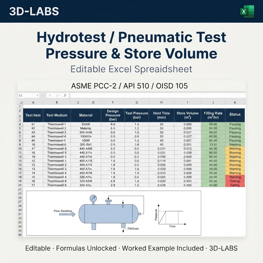
Hydrotest / Pneumatic Test Pressure & Stored Energy — method, governing standards and output schedule
The Hydrotest / Pneumatic Test Pressure & Stored Energy calculation quantifies a hazard or the integrity duty associated with it, and reports the protective measure, exposure limit or inspection interval that the result requires. It is applied during detailed design, during design verification by a second engineer, and again during in-service assessment when the operating basis changes. Because every intermediate quantity is reported rather than only the final answer, the calculation can be checked line by line against the governing standard without re-deriving it.
This 3D-LABS workbook is built to IEC 61511. You supply 10 inputs and the sheet reports 6 results, with every formula left visible so each figure can be traced to the clause it comes from.
Method of calculation
The hazard is modelled by the recognised method for its class: incident energy and boundary distances from the arc-flash equations, downwind concentration from the Gaussian plume model with the stability-dependent dispersion coefficients, radiant heat flux from the pool fire view factor, or overpressure from the multi-energy blast curves. Integrity duties are set from the measured degradation rate against the minimum acceptable condition, with the interval capped at a fraction of the calculated remaining life.
Governing standards and references
- IEC 61511 — IEC 61511 Functional safety – Safety instrumented systems for the process industry sector
- API 580/581 — API RP 580 and RP 581 Risk-Based Inspection methodology
Each formula cites the clause it comes from on the same row as the result it produces, so a reviewer can check the sheet line by line against the standard.
Acceptance criteria
For the calculation to be reported as acceptable, the calculated exposure must be reduced below the applicable occupational or tolerability limit by the selected protective measure, and inspection intervals must not exceed the code cap or half the calculated remaining life, whichever is the lesser.
Who uses this calculation
This calculation is used by process safety, HSE and inspection engineers, and authorities reviewing safety cases and integrity management programmes.
What you receive
- Excel calculation file (.xlsx) — fully unlocked formulas and a clear input/output layout
- Worked example — realistic engineering values with expected outputs so you can verify the sheet against a known case
- Code references — every formula cross-referenced to IEC 61511
- Email support — write to info@3d-labs.com with questions about inputs, methodology or results
Delivery and licence
Instant download after payment at ₹2,199. One payment, lifetime access, no subscription. The workbook is a design aid — results must be verified by a qualified engineer before use.
What Hydrotest / Pneumatic Test Pressure & Stored Energy — Excel calculates
Hydrotest / Pneumatic Test Pressure & Stored Energy — Excel is an Excel-native engineering calculation tool built by 3D-LABS for mechanical, design, and equipment engineers working with pressure equipment, rotating machinery, and mechanical systems. It is used for sizing pressure vessels, heat exchangers, flanges, bolts, and other mechanical components. Every input is labelled and every output is traceable — the sheet is designed to be checkable, not a black box.
Codes and standards followed
Hydrotest / Pneumatic Test Pressure & Stored Energy — Excel follows industry-standard Mechanical Engineering codes including ASME VIII Div 1 & 2, ASME B16.5, TEMA, API 660, HEI, EN 13445. Each formula is cross-referenced to the applicable code clause so your reviewer can trace calculations back to the standard.
If your project requires a different code base (e.g. converting an IS-code sheet to an ASME basis), we can produce a code-variant edition on request. Contact info@3d-labs.com for a variant quote.
What is included in your download
- The Excel calculation file (.xlsx) — fully unlocked formulas, cell-level comments, and a clear input/output layout.
- A sample worked example — realistic inputs plus expected outputs so you can validate the spreadsheet against a known case.
- User notes (PDF) — assumptions, code clauses referenced, and edge-case guidance.
- Revision history — every update to the spreadsheet is logged so you know what changed and when.
- Email support — reply within 24 hours (Monday to Saturday, IST) for questions about the spreadsheet or its use.
Software requirements
Hydrotest / Pneumatic Test Pressure & Stored Energy — Excel runs in Microsoft Excel 2016 or later on Windows and Mac. It is also compatible with LibreOffice Calc and can be imported into Google Sheets (some formatting may shift). No macros are required and no external add-ins are needed — every calculation runs in cell formulas, which means every step is auditable.
Pricing and delivery
Hydrotest / Pneumatic Test Pressure & Stored Energy — Excel is priced at ₹2,199 (approximate USD equivalent shown in the cart). Delivery is instant — after payment you get a download link immediately and a receipt by email. One-time purchase, lifetime access, no subscriptions or hidden fees.
Payment methods: Cashfree (Indian customers) or PayPal International (customers outside India). Volume discounts are available on bundles of 5 or more spreadsheets from the same discipline — contact sales@3d-labs.com for a bundle quote.
Related tools and services
Engineers who work with Hydrotest / Pneumatic Test Pressure & Stored Energy — Excel often also need:
- Other Mechanical Engineering spreadsheets from our catalogue of 119 tools in this discipline.
- Our Pressure Vessel Design Services — for projects where the calculation is only part of a larger scope and you want the full engineering deliverable produced by 3D-LABS.
- Our online training courses — instructor-led programmes on Mechanical Engineering topics, including software mastery and code walkthroughs.
- Our engineering e-book library — 115+ technical PDF references covering theory, practice, and code interpretation.
Frequently asked questions
What software do I need to run Hydrotest / Pneumatic Test Pressure & Stored Energy — Excel?
The spreadsheet is delivered as a native Excel (.xlsx) file. It runs in Microsoft Excel 2016 or later on Windows and Mac. It also runs in LibreOffice Calc and Google Sheets (with import), though some formatting may shift. No macros are required — all logic runs in cell formulas so you can audit every step.
Which codes and standards does this spreadsheet follow?
Hydrotest / Pneumatic Test Pressure & Stored Energy — Excel follows ASME VIII Div 1 & 2, ASME B16.5, TEMA, API 660, HEI, EN 13445. Every formula is cross-referenced to the code clause it implements, so your reviewer can trace the calculation back to the standard. If your project needs a different code, contact us — many spreadsheets are available in code-variant editions.
Are the formulas locked or editable?
All formulas are unlocked and editable. You can adapt inputs, add your own load combinations, integrate the sheet into your own workflow, and audit the logic. We do not password-protect our worksheets — an engineer should always be able to verify what the tool is doing.
What is included in the download?
The download includes: (1) the Excel calculation file with all formulas, (2) a sample worked example showing typical inputs and expected outputs, (3) a short user notes PDF explaining assumptions and code clauses used, and (4) a revision history so you can see how the sheet has been updated over time.
Do you offer support if I have questions?
Yes. Email support with any 3D-LABS spreadsheet purchase — reply within 24 hours (Mon-Sat, IST). We also offer paid tuning if you need the spreadsheet adapted to a specific project (typically USD 50-200 depending on scope). Contact info@3d-labs.com for details.
About 3D-LABS engineering spreadsheets
Hydrotest / Pneumatic Test Pressure & Stored Energy — Excel is one of 680 engineering calculation spreadsheets in the 3D-LABS catalogue — the largest curated collection of code-compliant Excel calculators for practising engineers anywhere. Each sheet is built and reviewed by 3D-LABS engineers who use them daily on real client projects across pressure vessel design, storage tank design, piping stress analysis, structural engineering, heat exchanger design, and FEA services since 2003.
Browse the full SpreadSheet Calculations catalogue or the Mechanical Engineering calculations sub-category. Volume discounts apply on 5+ spreadsheets from the same discipline.
Why buy from 3D-LABS
Built by a working engineering practice
3D-LABS has designed pressure vessels, storage tanks, piping and structures since 2003 for operators and EPC contractors across Asia, the Middle East, Africa and Australia. Our calculation sheets are produced by that same engineering team, to the codes we work to every day.
- 2003Engineering since
- 12Countries delivered into
- 50+Named client organisations
- 14Design codes worked to
Codes our engineers design to
- ASME
- API 650
- API 620
- AWWA D103
- AS 2304
- AS 1210
- TEMA
- PD 5500
- AISC
- IS 800
- EN 1993-4-1
- IBR
- IBC
- BS
Found something that does not work as you expected? Tell us — a working engineer answers, not a support desk.Design and detailing for Larsen & Toubro, Emerson, PetroFac, Qatar Petroleum, ADCO and Samsung Engineering since 2003.